Federal Motor Vehicle Safety Standards; Child Restraint Anchorage Systems; Child Restraint Systems
This NPRM responds to petitions for reconsideration of the January 7, 2025 final rule amending Federal Motor Vehicle Safety Standard (FMVSS) No. 225. NHTSA proposes granting the...
National Highway Traffic Safety Administration (NHTSA), Department of Transportation (DOT).
ACTION:
Notice of proposed rulemaking; response to petitions for reconsideration, technical corrections.
SUMMARY:
This NPRM responds to petitions for reconsideration of the January 7, 2025 final rule amending Federal Motor Vehicle Safety Standard (FMVSS) No. 225. NHTSA proposes granting the requests to extend the 3-year phase-in period to a 4-year phase-in period to comply with updated requirements in FMVSS No. 225 and to
( printed page 49386)
extend the lead time for small-volume manufacturers to comply fully with the updated requirements by the end of the proposed phase-in period. The agency also proposes granting the request to extend the sunset of the tether anchorage exemption for convertibles by two years. NHTSA proposes denying the request to allow tether routing over adjustable or removable head restraints to meet the tether anchorage location requirements. NHTSA is also proposing to make several technical corrections, and clarify certain test procedures.
DATES:
Comments must be received by September 3, 2026.
Proposed Compliance Dates:
NHTSA proposes adopting a 4-year phase-in period to comply with the updated requirements in FMVSS No. 225 and proposes extending the lead time for small-volume manufacturers to comply fully with the updated requirements by the end of the proposed phase-in period. The agency also proposes extending the sunset date of the tether anchorage exclusions for convertibles by two years. NHTSA proposes to permit early compliance.
ADDRESSES:
You may submit comments to the docket number identified in the heading of this document by any of the following methods:
Federal eRulemaking Portal:
Go to
www.regulations.gov.
Follow the online instructions for submitting comments.
Mail or Hand Delivery:
Docket Management, U.S. Department of Transportation, 1200 New Jersey Avenue SE, West Building, Suite W58-213, Washington, DC 20590, between 9 a.m. and 5 p.m., Monday through Friday, except on Federal holidays. To be sure someone is there to help you, please call (202) 366-9826 or (202) 366-9317 before coming.
Fax:
202-493-2251.
Regardless of how you submit your comments, please mention the docket number of this document.
Instructions:
For detailed instructions on submitting comments and additional information on the rulemaking process, see the Public Participation heading of the
Supplementary Information
section of this document. Note that all comments received will be posted without change to
www.regulations.gov,
including any personal information provided.
Docket:
For access to the docket to read background documents or comments received, go to
www.regulations.gov,
or the street address listed above. Follow the online instructions for accessing the dockets.
Confidential Business Information:
If you claim that any of the information in your comment (including any additional documents or attachments) constitutes confidential business information within the meaning of 5 U.S.C. 552(b)(4) or is protected from disclosure pursuant to 18 U.S.C. 1905, please see the detailed instructions given under the Public Participation heading of the
Supplementary Information
section of this document.
Privacy Act:
Please see the Privacy Act heading under the Regulatory Analyses section of this document.
FOR FURTHER INFORMATION CONTACT:
For technical issues, you may contact Cristina Echemendia, Office of Crashworthiness Standards, at
cristina.echemendia@dot.gov.
For legal issues, you may contact John Piazza, Office of Chief Counsel, at
john.piazza@dot.gov.
You can reach these officials by phone at 202-366-1810. Address: National Highway Traffic Safety Administration, U.S. Department of Transportation, 1200 New Jersey Avenue, SE, West Building, Washington, DC 20590.
SUPPLEMENTARY INFORMATION:
Table of Contents
I. Background
II. Petitions for Reconsideration and NHTSA's Response
a. Extend 3-Year Phase-In to 4-Year Phase-In
b. Extend Lead Time and Phase-In for Small Volume Manufacturers
c. Extend the Sunset Date of Tether Anchorage Exemption for Convertible Vehicles
d. Allow Tether Strap Routing Over Adjustable or Removable Head Restraints To Meet New Tether Anchor Location Requirement
e. Extend Permissible Vertical Measurement To Locate Lower Anchorage Markings
f. Clarify Test Procedure to Position Clearance Angle Tool in Some Vehicles
III. Corrections and Clarifications to Regulatory Text
a. Figure Reference in S6.2.2 of FMVSS No. 225
b. Test Procedure To Position Anchorage Depth Tool in FMVSS No. 225
c. Compliance Date in S5.9(c) of FMVSS No. 213b
d. Location of Tether Marking for Flexible Tether Anchorages That Are Also Routing Devices
e. Force Direction S11(a)(1) and (2)
f. 49 CFR 585.140 Reporting Requirements for Vehicles Produced by More Than One Manufacturer
g. Clarification of Length Measurement of Tether Hardware Assemblies
IV. Costs and Benefits
V. Proposed Compliance Dates
VI. Regulatory Analyses and Notices
I. Background
On January 7, 2025, NHTSA published a final rule (90 FR 1288) amending FMVSS No. 225, “Child restraint anchorage systems,” to improve ease-of-use of the lower and tether anchorages and improve correct use of child restraint systems in motor vehicles.
NHTSA's regulations allow any interested person to petition the Administrator for reconsideration of a rule.[1]
Under NHTSA's regulations, petitions for reconsideration must provide an explanation why compliance with the rule is not practicable, is unreasonable, or is not in the public interest. Petitions must be received within 45 days of the publication of the final rule. The Administrator may, consistent with 5 U.S.C. 553, issue a final decision on reconsideration without further proceedings or may provide opportunity for comment.
NHTSA received petitions for reconsideration of the January 7, 2025 final rule from Alliance for Automotive Innovation (Alliance) and Mercedes-Benz Research & Development North America, Inc (Mercedes-Benz).[2]
In this notice of proposed rulemaking (NPRM), NHTSA proposes granting Mercedes-Benz's request to change the 3-year phase-in period to a 4-year phase-in period and granting Alliance's requests to amend the phase-in schedule for small volume manufacturers [3]
and to extend the sunset of the tether anchorage exemption for convertibles by 2 years. NHTSA proposes denying Mercedes-Benz's requests to allow tether routing over adjustable or removable head restraints to meet the new tether location requirement and to extend the permissible vertical transverse plane measurement to locate lower anchorage markings. The agency is also proposing minor technical corrections to the regulatory text and is providing clarification on the use of the clearance angle tool requested by Mercedes-Benz.
NHTSA seeks comment on all aspects of this NPRM.
II. Petitions for Reconsideration and NHTSA's Response
a. Extend 3-Year Phase-In to 4-Year Phase-In
The January 7, 2025 final rule established a three-year phase-in
( printed page 49387)
schedule to comply with the updated FMVSS No. 225 requirements, as follows: 20 percent of applicable vehicles produced from September 1, 2028 to August 31, 2029, 50 percent from September 1, 2029 to August 31, 2030, and 100 percent beginning September 1, 2030. Mercedes-Benz petitioned the agency to change the three-year phase-in schedule to a four-year phase-in schedule to meet the updated requirements in FMVSS No. 225. In support of its petition, Mercedes-Benz stated that a four-year phase-in schedule “would lessen the burden for manufacturers to redesign the body-in-white and seat structure for vehicles currently in mid-life cycle.” [4]
Based on information provided by Mercedes-Benz, NHTSA tentatively concludes that to meet the updated FMVSS No. 225 requirements, several vehicle models would require structural redesign in mid-life cycle. This would involve an iterative process for redesigning structural components of the vehicle and seats, and the seat foam, and validating the design to the updated requirements. Changes to the structural and seat foam design would also necessitate changes to production tooling that could add to manufacturing delays. All of this involves non-trivial lead time, and this challenge is magnified when the changes occur off-cycle.
Accordingly, NHTSA proposes extending the phase-in schedule from a three-year phase-in to a four-year phase-in as requested by Mercedes-Benz. This extension would ease the burden of redesigning vehicles by reducing costs and providing additional time to plan and implement the necessary changes to the affected vehicles. This additional phase-in year would reduce potential tooling costs by allowing manufacturers the opportunity to make required changes to subject vehicles during their regular design update cycles. The proposed phase-in schedule to comply with the FMVSS No. 225 updated requirements, which is in accordance with the petitioner's request, is as follows:
20 percent of applicable vehicles produced from September 1, 2028 to August 31, 2029;
50 percent from September 1, 2029 to August 31, 2030;
75 percent from September 1, 2030 to August 31, 2031; and
100 percent of applicable vehicles on and after September 1, 2031.
NHTSA explained in the January 2025 final rule that the intent of the phase-in schedule was to provide sufficient time for vehicle manufacturers to accommodate significant vehicle system changes into manufacturers' normal course of vehicle redesign. Providing an additional year to the phase-in schedule would allow manufacturers to meet the requirements of this final rule with minimal cost impacts consistent with the intent of the January 2025 final rule.
b. Extend Lead Time and Phase-In for Small Volume Manufacturers
Alliance petitioned NHTSA to provide additional lead time for small volume manufacturers (SVM) [5]
to comply with the updated requirements. Specifically, Alliance's petition asked that the phase-in schedule for SVMs be removed and replaced with 100% compliance by September 1, 2030 to minimize additional manufacturing costs.
Alliance stated the additional lead time is necessary to address the regulatory burden unique to SVMs, explaining that because of their small volume and unique product lifecycles, SVMs encounter more planning constraints and do not benefit from phase-in schedules like larger vehicle manufacturers may. In support of its petition, Alliance explained that modifications to the seating system, the overall vehicle architecture, or both will be necessary to meet the new requirements. Alliance stated that SVMs typically do not have a larger parent company that can benefit from base-vehicle platforms shared across multiple models or brands to spread overall development and manufacturing costs. Alliance added that given lower sales volumes, the relative investment to redesign SVM vehicles is often more substantial per model line compared to larger vehicle manufacturers. Further, Alliance stated that financial capital and human resource constraints for SVMs are often very different from those of large volume vehicle manufacturers.
NHTSA proposes granting Alliance's request to extend the lead time for SVMs. The agency understands that SVMs might need more time to make vehicle design changes and that such changes may trigger added costs due to SVMs' longer design cycles. Given the unique design cycles of SVMs, NHTSA is proposing to eliminate the phase-in period to meet the updated requirements in FMVSS No. 225 and instead require SVMs to comply by the proposed compliance date. The petitioner requested September 1, 2030 as the compliance date for SVMs, but because the agency is proposing to grant Mercedes-Benz's request and extend the phase-in period for non-SVMs by one year (to 2031), NHTSA is proposing September 1, 2031 as the compliance date for SVMs, with no phase-in.
This proposal is consistent with the general lead time concerns addressed in the January 7, 2025 final rule, which acknowledged that design changes such as body structure reinforcement and re-design, changes to the seat and anchorages, and in some cases development of new attachment schemes would be necessary for production vehicles to meet the updated requirements. Specifically, NHTSA extended the lead time in the final rule to provide sufficient time for vehicle manufacturers to accommodate any vehicle system changes into manufacturers' normal course of vehicle redesign while also mitigating cost impacts.
c. Extend the Sunset Date of Tether Anchorage Exemption for Convertible Vehicles
The FMVSS No. 225 standard established in 1999 excluded convertibles from having to provide tether anchorages in rear seating positions.[6]
This exclusion was created in response to comments to the 1997 NPRM,[7]
where GM and Mitsubishi stated that vehicle manufacturers have technical problems installing tether anchorages in convertibles because the vehicles have folding roofs, a stowage area behind the seat back for the top and its mechanism, and less rear seat space. NHTSA agreed that many convertibles could have design problems and determined that it could not at that time readily separate those convertibles from those without technical problems.
The 2015 NPRM requested comments on the feasibility of installing tether anchorages in convertibles because several convertible vehicle models in the market have demonstrated that they can accommodate tether anchorages.[8]
Specifically, the agency found that among 35 convertible vehicle models from the 2013 vehicle fleet, 10 were equipped with lower anchorages and tether anchorage in two rear designated seating positions (DSPs), 14 were equipped with only the lower
( printed page 49388)
anchorages at two rear DSPs, and 11 were not equipped with any anchorages. The 2025 final rule established that convertibles manufactured after September 1, 2031 would be required to be equipped with tether anchorages.
Alliance petitioned the agency to extend the sunset date of the tether anchorage exclusions for convertibles from September 1, 2031 to September 1, 2033. Alliance explained that the design changes for convertible vehicles often occur after the architecture for coupe models has been established, causing these models to follow a longer design cycle, and requiring additional time to minimize the burden of modifying an already developed vehicle architecture. Alliance added that the implementation of the top tether anchorage is challenging because of the unique design of convertible models, which is more complex than coupe variants because of the roof mechanism and the low clearance available to install the anchorage.
NHTSA proposes to grant Alliance's request to extend the sunset date of the tether anchorage exclusions to September 1, 2033. The agency understands that convertibles may present unique design challenges and that these models might follow longer design cycles. NHTSA tentatively concludes that extending the sunset date for the exemption for convertibles will help accomplish the final rule's intent of increasing tether availability while also minimizing costs. NHTSA requests comment on the proposal for a two-year extension of the sunset date of the exemption for convertibles from tether anchorage requirements.
NHTSA also proposes to extend the sunset date of the exception for lower anchorages in rear designated seating positions where interference with the transmission or suspension components prevent the location of the lower anchorages anywhere in the specified zones in S5.1(e) of FMVSS No. 225. This provision mostly affects convertible vehicles and aligning the sunset dates for the exception of both the tether anchorages and the lower anchorages in convertibles will help streamline the design development of child restraint anchorage systems in these vehicles.
d. Allow Tether Strap Routing Over Adjustable or Removable Head Restraints To Meet New Tether Anchor Location Requirement
The 2025 final rule adopted a new requirement for DSPs with either adjustable, removable, or no head restraint to locate the tether anchorage outside a specified zone. This zone is defined by a 325-millimeter (mm) radius sphere centered on the R-point [9]
and horizontally truncated 230 mm below the sphere's center. This measurement was adopted to ensure sufficient space exists between the tether anchorage and the tether attachment on the child restraint for a caregiver to tighten the tether strap. The 2025 final rule excluded DSPs with fixed head restraints from the tether anchorage location requirements specified by the 325-mm sphere centered on the R-point. This exclusion was made because DSPs with fixed head restraints require the tether to be routed over the fixed head restraint. This extended tether routing length provides sufficient space to effectively tighten the tether strap. In addition, because there is no interference of fixed head restraints during tether routing and tightening, the zone where tether anchorages cannot be located, defined by the 325-mm radius sphere, is unnecessary for DSPs with fixed head restraints.
Mercedes-Benz petitioned NHTSA to allow for tether strap routing over adjustable or removable head restraints if such tether strap routing meets the required minimum wraparound distance of 325 mm from R-Point to the tether anchorage location.[10]
Mercedes-Benz stated that the tether strap routing over adjustable or removable head restraints “should be included and described in the Operator's Manual.” Mercedes-Benz argued that this belt length is sufficient and allows for easy tether fixation but is not currently permitted in the final rule. In support of its request, Mercedes-Benz stated, in a meeting with NHTSA,[11]
that NHTSA's own research indicates that routing the tether under or over an adjustable head restraint did not have an effect on head excursion. Mercedes-Benz added that to meet the new tether anchorage location requirements, Mercedes-Benz's body-in-white and seat structures must be redesigned to move the tether anchorage rearward by 75 mm.[12]
Mercedes-Benz explained their current design includes structural reinforcements for this anchorage and that redesigning this area will incur significant time and development costs.
On July 25, 2025, NHTSA received a joint letter from Volkswagen Group of America (Volkswagen) and Porsche Cars North America (Porsche) in support of Mercedes-Benz's petition for reconsideration to allow tether strap routing over adjustable head restraints if such tether strap routing meets a required minimum wraparound distance of 325 millimeters from R-point to the tether anchor location.[13]
Volkswagen and Porsche also requested that the 325-millimeter radius sphere, with its center at the R-point, that is used for establishing a zone where tether anchorages cannot be located, be truncated 155 millimeters below the sphere's center instead of the current 230 millimeters below the sphere's center. Volkswagen and Porsche noted that this modification to the final rule regulatory text would permit tether anchorage locations in current sport utility vehicles (SUVs) that otherwise would be prohibited by the January 7, 2025 final rule. Volkswagen and Porsche also noted that the tether anchorages at their current location in SUVs have not hindered attaching and tightening the tether.
NHTSA has tentatively decided to deny Mercedes-Benz's request to allow routing the tether strap over adjustable or removable head restraints. The January 7, 2025 final rule already considered and responded to comments raising concerns that relocating tether anchorages might require tooling and manufacturing changes. In response to these comments, the agency provided an extended lead time followed by a phase-in period to comply with the updated requirements so that those changes could be made during regular vehicle design updates to mitigate cost.
The NHTSA-funded research that Mercedes-Benz referred to in the July 23, 2025 meeting is a study conducted by the University of Michigan Transportation Research Institute (UMTRI).[14]
The results of this study suggest that there is not a particular method of routing the tether that provides the greatest safety benefit in terms of reduced head excursion.
( printed page 49389)
Rather, the lowest head excursions were associated with routing and tether locations that involved the shortest amount of tether webbing between the tether anchor and the attachment point on the child restraint, provided the tether could be adequately tightened. UMTRI noted in another NHTSA-funded study, however, that tether routing over the head restraint could result in the tether slipping to the side of the head restraint in oblique and side impact crashes, resulting in greater head excursions.[15]
The current best practice followed by child passenger safety technicians is to route the tether strap under adjustable head restraints or to remove the head restraint for practical and safety considerations.[16]
Most manufacturers, including Mercedes-Benz, Volkswagen, and Porsche, currently recommend in their owner's manual to route the tether under adjustable head restraint or to remove the head restraint.
The January 2025 final rule explained that because some head restraints that protrude or tilt to the front could interfere with the installation of some CRS models, it is typically advised to remove or move the head restraint to a higher position to eliminate this interference. If the vehicle was designed to meet the tether location requirement while routing the tether over the head restraint and the head restraint is removed because of CRS-head restraint interference, it is possible that the tether anchorage would not be at a sufficient distance from the back of the CRS that would permit tightening the tether. As explained in the final rule, NHTSA determined that because adjustable or removable head restraints are likely to be used with a tether routed under the head restraint, it is important to have the tether anchorage beyond the 325 mm truncated sphere from the R-point to ensure tethers can be tightened easily. Routing the tether over a head restraint placed in its highest position to avoid interference with a child restraint would increase the tether strap length resulting in higher head excursions and a greater risk of head injuries.
Another safety concern with routing the tether over a head restraint placed in a high position to avoid interference with a child restraint is that there are no strength requirements for the head restraint to withstand tether loads; therefore, the head restraint may not remain sufficiently fixed in position relative to the seat back. The head restraint might shift to a lower position or separate from the seat back, resulting in tether slack and higher head excursions.
For these reasons, which were discussed generally in the January 2025 final rule, NHTSA has decided tentatively to deny Mercedes-Benz's request to allow tether routing over adjustable/removable head restraints to meet the tether location requirement.
NHTSA also does not propose, as requested by Volkswagen and Porsche, to truncate the 325-millimeter sphere at 155 millimeters below the center of the sphere to continue to permit tether anchorage locations in the seatbacks of their current SUVs. Volkswagen and Porsche did not provide specific data showing that this allowance in the location of the tether anchorages would allow tightening the tether of child restraints in a variety of vehicle designs. In a NHTSA-funded study, UMTRI evaluated nine vehicle models with tether anchorages located on the seatback and found that seven of these vehicles (78 percent) met the January 2025 final rule specifications for tether anchorage location.[17]
The remaining two vehicles needed only minor modifications (one to two centimeters) to the tether anchorage location on the seat back to meet the January 2025 final rule specifications. If the 325-millimeter sphere, truncated at 155 millimeters below the center of the sphere was applied to these two vehicles, and the tether anchorage was placed at the outside edge of this boundary, the tether anchorage would be too close to the head restraint (less than 165 mm) and would likely be difficult to tighten. Therefore, NHTSA concludes tentatively that Volkswagen and Porsche's requested modification to the allowable location zone for the tether anchorages would not ensure that the tether strap of child restraints can be sufficiently tightened in all vehicles.
The January 7, 2025 final rule specifications for allowable tether anchorage locations using the 325 millimeter sphere centered at the R-point of the seat and truncated 230 millimeters below the R-point harmonize with the requirements in the Australian Design Rule 34/02 “Child Restraint Anchorages and Child Restraint Anchor Fittings.” [18]
The January 2025 final rule tether anchorage location requirements were designed to prevent possible conflicts with the June 2016 Insurance Institute for Highway Safety (IIHS) Vehicle LATCH Hardware Evaluation Rating Guidelines [19]
such that tether anchorages located on the seatback that meet the January 2025 final rule requirements could also obtain higher IIHS scores.
Based on the diagrams presented in the Volkswagen-Porsche letter, the tether anchor location on the seatback would need only minor adjustments to meet the January 2025 final rule specifications for tether anchorage location. NHTSA concludes tentatively the additional one-year phase-in period would allow the manufacturers to make any needed vehicle changes within their normal design cycle to meet the tether anchorage location requirements specified in the January 7, 2025 final rule.
e. Extend Permissible Vertical Measurement To Locate Lower Anchorage Markings
Before the January 2025 final rule, FMVSS No. 225 required lower anchors that are not visible to be marked with a circle that is not less than 13 mm in diameter located on the seatback area at a vertical distance between 50 and 100 mm above the anchorage or on the seat cushion at a horizontal distance 100 ±25 mm forward of the anchorage. This is illustrated in figure 22 of FMVSS No. 225.
The January 2025 final rule updated the requirements for lower anchor markings and their location. The final rule required all lower anchorages to be marked, regardless of whether they are visible, with a circle not less than 13 mm in diameter displaying the International Standards Organization (ISO) lower anchorage symbol (figure 24 of FMVSS No. 225). The final rule also expanded the permissible location of the marking on the seat cushion to
( printed page 49390)
accommodate seat contours where the marking can be visible when positioned behind the lower anchor. Specifically, the final rule specified that, if the manufacturer chooses to locate the marking on the seat cushion, it must be placed at a horizontal distance between 100 mm forward and 50 mm rearward of the horizontal centerline of the lower anchorage bar. The final rule did not change the location requirements for markings placed on the seatback. The final rule placed an illustration of the updated marking location requirements in Figure 19 of the standard.[20]
The final rule placed the current requirements in S9.5.1 and the updated requirements in S9.5.2.
Mercedes-Benz requested that NHTSA extend the permissible Vertical Transverse Plane (the “a” measurement in Figure 19 of the standard, reproduced in Figure 1 below) to locate the lower anchorage marking symbol on the seat back of the vehicle from the specified 50 to 100 mm range to a range from negative 50 to 100 mm. Mercedes-Benz stated that this change would allow the markings to be located on the molded anchorage rod fixture while still being easily visible to CRS installers.[21]
NHTSA is denying Mercedes' request as unnecessary. In the June 27, 2003 final rule that is the source of the current requirements in S9.5.1,[22]
the agency changed the original requirement, which consisted of only a vertical placement distance for the marking (seat back), to one that also allowed a horizontal placement for the marking on the seat pan. The 2003 final rule implemented this change in response to comments from Mitsubishi and the Alliance, who asked where the “seat back” begins for the purpose of marking the lower anchorages on highly contoured seats. Specifically, Mitsubishi stated that the bottom cushion of some of its seats curves toward the vertical and supports a portion of an occupant's lower back before a separate seat back begins. To address this issue, the 2003 final rule adopted the location requirements from Transport Canada Regulation 210.2, “Lower Universal Anchorage Systems for Restraint Systems and Booster Cushions,” which had vertical (seat back) and horizontal (seat pan) allowable locations for the marking. In support of this decision, the agency explained that these location requirements provide greater clarity in relation to where the markings should be while also permitting the markings to be located either on the seat back or the seat cushion, and thus allowing more flexibility to manufacturers with atypical seat designs.
Though NHTSA changed some of the allowable distances for the markings in the January 7, 2025 final rule, the intent of the 2003 final rule was maintained. The 2025 final rule continues to permit markings to be placed on the seat back or the seat pan. The different allowable distances already provided by the final rule should provide flexibility to manufacturers with atypical seat designs in relation to where to place the lower anchorage markings. In the example Mercedes-Benz provided in its petition, the marking would be within the allowable seat pan “b” locations. Therefore, NHTSA denies Mercedes-
( printed page 49391)
Benz's request to change the seat back “a” distance. In support of this decision, NHTSA notes that for atypical seats with an extra bolster in the seat bight region (the area where a seat cushion intersects with the seatback) that helps transition the seat pan to the seat back, the bolster may be considered as part of the seat back or seat pan location to locate the marking within the “a” or “b” locations illustrated in Figure 19 of FMVSS No. 225.
In light of the request from Mercedes, NHTSA proposes to modify the regulatory text for both the current requirements (S9.5.1(a)(3)) and the updated requirements (S9.5.2(a)(3)) to clarify the permissible marking locations. NHTSA is also proposing to amend Figure 19 to FMVSS No. 225 so that the “b” measurement is specified as a continuous interval (Figure 2) instead of broken into positive and negative segments (Figure 1).
f. Clarify Test Procedure to Position Clearance Angle Tool in Some Vehicles
A 2012 LATCH Usability study performed by UMTRI identified three vehicle lower anchorage hardware characteristics serving as predictors for correct CRS use, which include anchorage depth, anchorage attachment force, and anchorage clearance angle.[23]
Anchorage depth refers to how deeply the lower anchorages are embedded in the vehicle seat (usually in the seat bight or seatback). Attachment force refers to the force needed to attach a child restraint's lower anchorage connector to a lower anchorage in a vehicle. Clearance angle refers to the clearance around a lower anchorage from parts that interfere with the ability to maneuver the CRS lower anchorage connector. UMTRI showed that subjects were 19 times more likely to install the CRS correctly if the vehicle met all three usability criteria than if none of the criteria were met.
Based on this study, NHTSA proposed in the 2015 NPRM [24]
to adopt the three characteristics measured by three different tools per the following:
○
Attachment force:
Less than 178 N (40 lb).
○
Clearance Angle:
Greater than 54 degrees when applying a 66.7 N (15 lb) vertical force to the tool.
○
Anchorage Depth:
Less than 2 cm.
Commenters to the 2015 NPRM expressed concerns on the repeatability of the usability measurements. NHTSA conducted repeatability and reproducibility studies where the proposed tools were updated to ensure better repeatability. Results of the studies and tool updates showed that the clearance angle and anchorage depth measurements were repeatable, but the attachment force measurement was not repeatable. Therefore, the 2025 final rule adopted only the clearance angle and anchorage depth measurements into FMVSS No. 225.
One of the repeatability improvements developed for the 2025 final rule clearance angle tool was adding a pulley bridge to position a weight that would apply a constant 66.7 N (15 lb) vertical force, as commenters were concerned about the difficulty of applying manually and keeping a constant vertical force to make the clearance angle measurement.
Mercedes-Benz petitioned NHTSA to “evaluate the Clearance Angle Tool (CAT) in a smaller two-door sport/coupe vehicle.” Mercedes-Benz explained that it is not clear from the final rule how the “pulley bridge” should be placed in vehicles with integrated headrests on the front and rear seat.[25]
In addition to its CAT concerns, Mercedes-Benz petitioned NHTSA to allow the use of the IIHS Clearance Angle Tool.
NHTSA acknowledges that the regulatory text in FMVSS No. 225 does not specify how to position the pulley bridge of the clearance angle tool on the vehicle. However, NHTSA's research test procedure [26]
describes how to position the pulley bridge as follows:
( printed page 49392)
Place the pulley bridge so it rests on the tops of the rear and front seatbacks above the lower anchor. Use the leveling feet to position the bridge so it is horizontal within ±5 degrees about its longitudinal axis. If necessary, change the front seatback angle to help level the pulley bridge.
In response to the concerns raised by Mercedes-Benz, NHTSA experimented with other vehicles in which there may be similar difficulty placing the pulley bridge on the rear and front seat backs. NHTSA found that placing a metal bar on the windowsill of the front row windows can help position the pulley bridge on those vehicles where it is not possible to place the pulley bridge on the front seat. This approach showed that, for vehicles with this configuration, the front seat can be moved, removed, or reclined in such a way so as not to interfere with the placement of the pulley bridge. In response to petitioner's concerns and to assist with future testing, NHTSA will docket an updated research test procedure [27]
to include information explaining how other vehicle structures and other structures could be used to position the pulley bridge if the front and rear seats cannot be used.
NHTSA is not codifying this step in the regulatory text of FMVSS No. 225 because the agency believes it is more appropriate to include this detailed information in the test procedure to help entities understand how to position the pulley bridge in the required position to make the clearance angle measurement appropriately.
In addition, NHTSA denies Mercedes-Benz's request to align or allow use of the IIHS clearance angle tool for measuring the clearance angle in FMVSS No. 225. The 2015 NPRM proposed using a clearance angle tool based on the IIHS tool and NHTSA received comments expressing concerns about the repeatability and reproducibility of that tool's measurements. Specifically, General Motors stated that it was difficult to apply the vertical force due to interference with the seat back, and Fiat Chrysler Automobiles U.S.[28]
commented that an operator would have difficulty maintaining 67 N (15 lbf) of vertical force to make the measurement. As explained in the January 2025 final rule, NHTSA added a pulley bridge (with adjustable feet to make it level) to apply a 67 N (15 lbf) force vertically to remove the difficulty of applying the specified load manually and address concerns raised by commenters.
III. Corrections and Clarifications to Regulatory Text
a. Figure Reference in S6.2.2 of FMVSS No. 225
Paragraph S6.2.2 of the January 7, 2025 final rule regulatory text referenced Figure 3 regarding the allowable tether anchorage zone under the vehicle seat, which is defined by a “vertical plane 120 mm rearward of the H Point.” However, Figure 3 in the standard shows the allowable tether anchorage location zone before the January 7, 2025 amendments and is not relevant to the updated allowable tether anchorage zone under the vehicle seat. The agency proposes to correct the figure reference in S6.2.2 to Figure 10, which shows the updated tether anchorage location zone and shows the new allowable tether zone under the vehicle seat.
b. Test Procedure to Position Anchorage Depth Tool in FMVSS No. 225
Paragraph S11(c) of FMVSS No. 225 describes the test procedure to measure the anchorage depth with the depth tool. However, this section lacks clarity on determining the view angles and positioning of the depth tool on the seat pan (see Figure 3). The research test procedure docketed [29]
along with the 2025 final rule details the procedure with the desired clarity. Accordingly, NHTSA proposes to amend S11(c) of FMVSS No. 225 to align with this research test procedure.
Specifically, NHTSA proposes changing the sentence “To measure the anchorage depth, subtract 30 degrees from the measured seat pan angle to calculate the view angle.” to “To measure the anchorage depth, the tool view angle is determined by subtracting the measured seat pan angle from 30 degrees.” NHTSA also proposes changing the sentence “Adjust the depth tool base to be within ±2 degrees of the view angle (30 degrees minus seat pan angle) to set the tool-parallel to the seat pan angle.” to “Adjust the depth tool base to be parallel with the seat pan angle (within ±2 degrees) while maintaining the established tool view angle (30 degrees minus seat pan angle).”
( printed page 49393)
c. Compliance Date in S5.9(c) of FMVSS No. 213b
NHTSA proposes correcting the compliance date indicated in S5.9 (c) of FMVSS No. 213b. Currently the date for the new requirements for tether hardware assembly to have a maximum length indicates a compliance date of January 8, 2025. On March 3, 2025, the agency issued a final rule specifying a 3-year lead time for several requirements adopted in the January 7, 2025 final rule. However, this correction indicated a January 8, 2025 compliance date in S5.9(c) by mistake, when it should state January 8, 2028 to match the corrections made to other sections in FMVSS No. 213b. The agency is proposing to correct paragraph 5.9(c) to state a January 8, 2028 compliance date.
d. Location of Tether Marking for Flexible Tether Anchorages That Are Also Routing Devices
The 2025 final rule amended FMVSS No. 225 to require all vehicles to bear the ISO standardized marking near all tether anchorages provided in the vehicle to improve the ease with which consumers find lower anchorages and tether anchorages in the vehicle.
NHTSA also adopted requirements for the tether markings to be no more than 100 mm away from the tether anchorage. For vehicles with tether strap routing devices, NHTSA permits placing the required tether anchorage marking on a tag attached to the tether strap routing device.
The January 7, 2025 final rule specified location requirements for the tether anchorage markings such that they are aligned and within 100 mm from the tether anchorage (S6.4 of FMVSS No. 225). While S6.4 section offers the option of using tags to mark tether strap routing devices,[30]
the regulatory text does not specify the location of the markings with respect to a flexible tether strap routing device that can be used as tether anchorages. The agency proposes correcting this omission by specifying the location of the marking with respect to the routing device that is consistent with the required location of the markings with respect to a rigid tether anchorage bar. The maximum distance of the marking from the routing device would remain the same as that from a rigid anchor (not more than 100 mm); however, the reference point on the routing device to measure the maximum distance of the marking is the intersection of the longitudinal [31]
and lateral [32]
centerline of the attachment of the routing device to the vehicle or vehicle seat in its nominal position,[33]
as illustrated in Figure 4 of this preamble. In the case of routing devices that may have multiple attachment points, the center of those attachment points would be the reference to measure the distance to the marking.
( printed page 49394)
e. Force Direction S11(a)(1) and (2)
Paragraphs S11(a)(1) and (2) of the regulatory text in the January 7, 2025 final rule specify the test procedure for applying forces to the lower anchorages to assess compliance with the strength requirements specified in S9.4.1(a) and (b), respectively. However, additional text introduced in the January 7, 2025 final rule is incorrect because it describes a horizontal preload force in S11(a)(1) and a preload perpendicular to the longitudinal centerline of the SFAD2 at point X of the test device in S11(a)(2). The preload force specified in S9.4.1(a) must be applied with an initial angle of 10 ± 5 degrees above the horizontal as described in S9.4.1.1. Also, the lateral load required in S9.4.1(b) is not perpendicular to the longitudinal plane but at a 75 ± 5 degree angle from the longitudinal plane. The agency proposes to correct the contradictory text in S11(a)(1) and (2) by deleting the added text.
f. 49 CFR 585.140 Reporting Requirements for Vehicles Produced by More Than One Manufacturer
Subpart O of 49 CFR 585 outlines the phase-in reporting requirements for FMVSS No. 225. Paragraph (b)(3) of § 585.140 addresses vehicles manufactured by more than one entity and currently references S13.2.1(c) of FMVSS No. 225. This reference is incorrect. The correct citation is S13.2.2. Accordingly, the agency proposes to amend § 585.140(b)(3) to replace the erroneous reference with the correct citation to S13.2.2.
g. Clarification on the Length Measurement of Tether Hardware Assemblies
NHTSA received a request for interpretation from Britax on October 27, 2025 [34]
seeking confirmation of its understanding of the test procedure for evaluating compliance with S5.9(c) of FMVSS No. 213b, which specifies that the length of the child restraint tether hardware assembly (which consists of the tether hook and hardware to tighten and loosen the tether strap) shall not exceed 165 mm.
Britax noted that NHTSA's Laboratory Test Procedure does not specify a measurement method. Britax also noted that its V-shaped tether hardware assembly, which is common in its products, differs from the single-strap tether designs NHTSA studied primarily. Britax stated that because a single strap tether hardware assembly has the adjustment mechanism located along the tether webbing in a fixed location relative to the tether hook, determining compliance with S5.9(c) simply requires measuring the length from the far end of the adjustment mechanism to the end of the tether hook. On the other hand, Britax noted that its V-shaped tether hardware assembly, consisting of a tether hook, two permanent tether strap webbing attachment points on the back of the CRS and a mechanism designed to adjust the tether strap webbing, would not be able to comply with the requirement that the tether hardware assembly length be no more than 165 mm in all adjustment positions if the measurement is made from the adjustment mechanism to the tether hook.
Due to the unique nature of the V-shaped tether hardware assembly with varying distance between the adjustment mechanism and the tether hook, Britax stated that to determine compliance with S5.9(c), it measures the distance from the center of the CRS seat back to the end of the tether hook after the tether strap is tightened. Britax stated that this aligns with NHTSA's stated goal for the 165 mm limit, which
( printed page 49395)
was to ensure all CRS tether straps can be tightened given the minimum tether anchorage distance from the seat back reference point, and that NHTSA was aware of and did not intend to outlaw the Britax design.
NHTSA is responding to Britax's request for interpretation in this NPRM. NHTSA disagrees with part of Britax's suggested measurement procedure—specifically, measuring the distance from the center of the CRS seat back to the end of the tether hook. This is not a correct interpretation of the requirement specified in the regulatory text. The regulatory text states that the length of the tether hardware assembly, which consists of a tether hook and a mechanism designed to tighten and loosen the tether strap, shall not exceed 165 mm. Because Britax's suggested measurement method does not include the adjustment mechanism, it does not conform to the regulatory text. NHTSA is therefore not proposing to include Britax's suggested measurement method in the regulation.
NHTSA, however, does agree with Britax's approach of tightening the tether strap prior to measuring the length of the hardware assembly. NHTSA acknowledges that the original regulatory text did not account clearly for an adjustable tether hardware assembly such as that in Britax's CRSs. NHTSA is therefore proposing two changes to the current regulatory text.
First, NHTSA is proposing to clarify in sections 5.9(b) and (c) of the FMVSS No. 213b what constitutes the tether hardware assembly. The current regulatory text indicates that the tether hardware assembly consists of “a tether hook and a webbing tightening mechanism designed to tighten or loosen the tether strap.” The agency is proposing to change this to “a tether hook and a mechanism designed to tighten and loosen the tether strap, including any material between those components.” This would more accurately describe the assembly because the CRS tether hardware sometimes has webbing or other materials attaching the tether hook to the tether adjustment mechanism.
Second, NHTSA is proposing to clarify that the length of an adjustable tether hardware assembly will be determined with the tether adjustment hardware as close to the tether hook as possible (“If the tether hardware assembly length is adjustable, its minimum adjusted length shall not exceed 165 mm”).
NHTSA notes that this proposed approach—tightening the tether strap prior to measuring the length of the tether hardware assembly—is the procedure NHTSA used in developing the January 2025 final rule. NHTSA documented in a technical report,[35]
submitted to the docket with the January 7, 2025 final rule, the tether hardware measurements NHTSA conducted on several CRSs, including Britax models with V-shaped tethers.[36]
All CRSs in that study except for the Britax CRSs had fixed-length tether hardware assemblies. To measure the length of the tether hardware assemblies for Britax's CRSs, NHTSA measured the V-shaped tether hardware assembly length with the tether strap pulled through the adjustment mechanism such that it resulted in the shortest distance possible between the tether hook and the adjustment mechanism, and the measurement was made from the end of the tether hook to the furthest point of the adjustment mechanism. The photographs in the technical report also illustrate the measurement method used for determining the length of the tether hardware assembly. This involved a fixture simulating a vehicle's tether anchorage, with a tape measure alongside it. The CRS tether hook is attached to the fixture's anchor to facilitate the measurement of the tether hardware against the tape measure. NHTSA's Office of Vehicle Safety Compliance is developing an updated laboratory test procedures manual, which may contain similar illustrations of the procedure.
NHTSA anticipates that Britax will be able to comply with the 165 mm requirement when evaluated using this procedure. All three Britax CRSs with V-shaped tether hardware assembly met the 165 mm requirement when evaluated by NHTSA using this method.[37]
In addition, Britax, in its comments to the 2015 NPRM,[38]
stated that its CRSs would be able to meet the 165 mm tether hardware length requirement.[39]
NHTSA seeks comment on these proposed amendments.
IV. Costs and Benefits
The proposed changes in compliance dates for FMVSS No. 225 would not result in additional costs; FMVSS No. 225 costs for these vehicles will simply be delayed.
NHTSA estimated the total cost of the updated requirements for anchorage markings and written instructions specified in the January 2025 final rule to be $1.73 million. This estimated cost would be delayed by the proposed changes in compliance dates. There may be additional cost savings associated with the proposed delay in the FMVSS No. 225 compliance dates because manufacturers have indicated to the agency that they may incur additional costs when making vehicle changes outside their planned design cycle and an extended compliance date would help reduce those costs.
NHTSA did not quantify benefits resulting from the January 2025 final rule. NHTSA stated only that if the updated requirements in the January 2025 final rule result in a 5 percent increase in correct installation using the lower anchorages and a 5 percent increase in tether use, it would save approximately 3 lives and prevent 6 moderate to higher severity injuries annually. Therefore, any benefits that could be delayed as a result of this proposal are speculative.
V. Proposed Compliance Dates
This NPRM proposes to amend the three-year phase-in period in the January 2025 final rule to a four-year phase in period to comply with the FMVSS No. 225 updated requirements. The proposed four-year phase-in for compliance with the FMVSS No. 225 updated requirements is as follows: 20 percent of applicable vehicles produced from September 1, 2028, to August 31, 2029, 50 percent from September 1, 2029, to August 31, 2030, 75 percent from September 1, 2030, to August 31, 2031 and 100 percent of applicable vehicles on and after September 1, 2031. This NPRM proposes amending the lead time for small-volume manufacturers to comply with the updated requirements in FMVSS No. 225 so that those manufacturers would now need to comply with the updated requirements starting on September 1, 2031.[40]
This NPRM also proposes to extend the sunset date of the tether anchorage exclusions for convertibles to September 1, 2033. The rest of the proposed amendments and corrections would have a compliance date corresponding
( printed page 49396)
to the compliance date of the section being amended.
NHTSA has considered the impact of this proposal under Executive Order (E.O.) 12866 and E.O. 14192. This rule has been determined to be not significant pursuant to E.O. 12866 and was not reviewed by the Office of Management and Budget (OMB) pursuant to that order.
The proposed update to FMVSS No. 225 is an E.O. 14192 deregulatory action.
Regulatory Flexibility Act
Pursuant to the Regulatory Flexibility Act (5 U.S.C. 601et seq.,
as amended by the Small Business Regulatory Enforcement Fairness Act (SBREFA) of 1996), whenever an agency is required to publish a notice of proposed rulemaking or final rule, it must prepare and make available for public comment a regulatory flexibility analysis that describes the effect of the rule on small entities (
i.e.,
small businesses, small organizations and small governmental jurisdictions), unless the head of an agency certifies the rule will not have a significant economic impact on a substantial number of small entities. Agencies must also provide a statement of the factual basis for this certification.
I certify that this rulemaking action would not have a significant economic impact on a substantial number of small entities. NHTSA estimates that there are three small light vehicle manufacturers in the U.S. The estimated annual vehicle sales for these three manufacturers range from 25 to 100 vehicles with a sales price range $24,000 to $750,000 and estimated annual revenue between $2 million and $4 million. This proposed rule reduces design and cost burden for these small volume manufacturers by extending the full compliance date to September 1, 2031 without any phase-in.
Federalism
NHTSA has examined this NPRM pursuant to E.O. 13132 (64 FR 43255, Aug. 10, 1999) and concluded that no additional consultation with States, local governments or their representatives is mandated beyond the rulemaking process. The agency has concluded that the rulemaking would not have sufficient federalism implications to warrant consultation with State and local officials or the preparation of a federalism summary impact statement. This proposed rule would not have “substantial direct effects on the States, on the relationship between the national government and the States, or on the distribution of power and responsibilities among the various levels of government.”
NHTSA rules can have preemptive effect in two ways. First, the National Traffic and Motor Vehicle Safety Act contains an express preemption provision stating that, if NHTSA has established a standard for an aspect of motor vehicle or motor vehicle equipment performance, a State may only prescribe or continue in effect a standard for that same aspect of performance if the State standard is identical to the Federal standard.[41]
It is this statutory command by Congress that preempts any non-identical State legislative and administrative law addressing the same aspect of performance.
The express preemption provision described above is subject to a savings clause under which “[c]ompliance with a motor vehicle safety standard prescribed under this chapter does not exempt a person from liability at common law.” [42]
Pursuant to this provision, State common law tort causes of action against motor vehicle manufacturers that might otherwise be preempted by the express preemption provision are generally preserved.
NHTSA rules can also preempt State law if complying with the FMVSS would render the motor vehicle manufacturers liable under State tort law. Because most NHTSA standards established by an FMVSS are minimum standards, a State common law tort cause of action that seeks to impose a higher standard on motor vehicle manufacturers will generally not be preempted. However, if and when such a conflict does exist—for example, when the standard at issue is both a minimum and a maximum standard—the State common law tort cause of action is impliedly preempted.[43]
Pursuant to E.O. 13132, NHTSA has considered whether this proposed rule could or should preempt State common law causes of action. The agency's ability to announce its conclusion regarding the preemptive effect of one of its rules reduces the likelihood that preemption will be an issue in any subsequent tort litigation. To this end, the agency has examined the nature (
e.g.,
the language and structure of the regulatory text) and objectives of this NPRM and finds that this proposed rule, like many NHTSA rules, prescribes only a minimum safety standard. Accordingly, NHTSA does not intend that this proposed rule preempt state tort law that would effectively impose a higher standard on motor vehicle manufacturers than that established by this proposed rule. Establishment of a higher standard by means of State tort law would not conflict with the minimum standard finalized in this document. Without any conflict, there could not be any implied preemption of a State common law tort cause of action.
National Environmental Policy Act
DOT has analyzed the environmental impacts of this notice of proposed rulemaking pursuant to the National Environmental Policy Act of 1969 (NEPA) (42 U.S.C. 4321et seq.). NHTSA has determined that this proposed rule is categorically excluded pursuant to 23 CFR 771.118(c)(4). Categorical exclusions (CE) are categories of actions that the agency has determined normally do not significantly affect the quality of the human environment and therefore do not require either an environmental assessment (EA) or environmental impact statement (EIS).[44]
In analyzing the applicability of a categorical exclusion, the agency must also consider whether extraordinary circumstances are present that would warrant the preparation of an EA or EIS.[45]
The Department's Operating Administrations (OAs) may apply CEs established in another OA's procedures.[46]
To do so, the Operating Administration “must evaluate the action for extraordinary circumstances identified in the OA procedures in which the CE is established to determine if a normally excluded action may have a significant impact and coordinate with the originating OA to ensure that the CE is being applied correctly.” [47]
This proposed rule, which would amend certain requirements and compliance dates in FMVSS Nos. 213b and 225, is categorically excluded pursuant to 23 CFR 771.118(c)(4): “Planning and administrative activities that do not involve or lead directly to construction, such as: Training, technical assistance and research; promulgation of rules, regulations, directives, or program guidance; approval of project concepts; engineering; and operating assistance to transit authorities to continue existing service or increase service to meet routine demand.” NHTSA has
( printed page 49397)
coordinated with the Federal Transit Administration (FTA) to ensure that this CE is being applied correctly. NHTSA does not anticipate any environmental impacts, and there are no extraordinary circumstances present in connection with this rulemaking.
Paperwork Reduction Act
Under the procedures established by the Paperwork Reduction Act of 1995 (PRA) (44 U.S.C. 3501,
et seq.), a Federal agency must request and receive approval from OMB before it collects certain information from the public and a person is not required to respond to a collection of information by a Federal agency unless the collection displays a valid OMB control number. This proposed rule would not have any requirements that are considered to be information collection requirements as defined by the OMB in 5 CFR part 1320.
Unfunded Mandates Reform Act (UMRA)
The Unfunded Mandates Reform Act of 1995 (2 U.S.C. 1531-1538) (UMRA) requires Federal agencies to assess the effects of regulatory actions that may result in the expenditure by a State, local, or Tribal government, in the aggregate, or by the private sector of $206 million (the value equivalent of $100 million in 1995, adjusted for inflation to 2025) or more in any one year. This proposed rule does not contain Federal mandates (under the regulatory provisions of Title II of the UMRA) for State, local and Tribal governments, or the private sector of $206 million or more in any one year. Thus, the analytical requirements of the UMRA do not apply to this action.
With respect to the review of the promulgation of a new regulation, section 3(b) of Executive Order 12988, “Civil Justice Reform” (61 FR 4729, February 7, 1996) requires that Executive agencies make every reasonable effort to ensure that the regulation: (1) specifies clearly the preemptive effect; (2) specifies clearly the effect on existing Federal law or regulation; (3) provides a clear legal standard for affected conduct, while promoting simplification and burden reduction; (4) specifies clearly the retroactive effect, if any; (5) defines key terms adequately; and (6) addresses other important issues affecting clarity and general draftsmanship under any guidelines issued by the Attorney General. This document is consistent with that requirement.
NHTSA has reviewed this rulemaking and determined that this rulemaking action conforms to the applicable standards in sections 3(a) and 3(b)(2) of E.O. 12988, Civil Justice Reform. The issue of preemption is discussed above in connection with E.O. 13132. NHTSA notes further that there is no requirement that an individual submit a petition for reconsideration or pursue other administrative proceedings before they may file suit in court.
National Technology Transfer and Advancement Act
Under the National Technology Transfer and Advancement Act of 1995 (NTTAA) (Pub. L. 104-113), “all Federal agencies and departments shall use technical standards that are developed or adopted by voluntary consensus standards bodies, using such technical standards as a means to carry out policy objectives or activities determined by the agencies and departments.” Voluntary consensus standards are technical standards (
e.g.,
materials specifications, test methods, sampling procedures and business practices) that are developed or adopted by voluntary consensus standards bodies, such as the International Organization for Standardization (ISO) and the Society of Automotive Engineers (SAE). The NTTAA directs this agency to provide Congress, through OMB, explanations when we decide not to use available and applicable voluntary consensus standards. There are no voluntary consensus standards developed by voluntary consensus standards bodies pertaining to this proposed rule.
Promoting International Regulatory Cooperation
The policy statement in section 1 of E.O. 13609 provides that the regulatory approaches taken by foreign governments may differ from those taken by the United States to address similar issues, and that in some cases the differences between them might not be necessary and might impair the ability of American businesses to export and compete internationally. It further recognizes that in meeting shared challenges involving health, safety, and other issues, international regulatory cooperation can identify approaches that are at least as protective as those that are or would be adopted in the absence of such cooperation and can reduce, eliminate, or prevent unnecessary differences in regulatory requirements.
NHTSA has analyzed this rule under the policies and agency responsibilities of E.O. 13609 and has determined this rulemaking will have no effect on international regulatory cooperation.
E.O. 13175 requires Federal agencies to consult and coordinate with Tribes on a government-to-government basis on policies that have Tribal implications, including regulations, legislative comments or proposed legislation, and other policy statements or actions that have substantial direct effects on one or more Indian Tribes, on the relationship between the Federal Government and Indian Tribes, or on the distribution of power and responsibilities between the Federal Government and Indian Tribes. NHTSA has assessed the impact of this proposed rule on Indian tribes and determined that this rule would not have Tribal implications that require consultation under E.O. 13175.
E-Government Act Compliance
NHTSA is committed to complying with the E-Government Act, 2002 to promote the use of the internet and other information technologies to provide increased opportunities for citizen access to Government information and services, and for other purposes. The E-Government Act of 2002 (Pub. L. 107-347, sec. 208, 116 Stat. 2899, 2921, Dec. 17, 2002), requires Federal agencies to conduct a privacy impact assessment for new or substantially changed technology that collects, maintains, or disseminates information in an identifiable form. No new or substantially changed technology would collect, maintain, or disseminate information as a result of this proposed rule. Accordingly, NHTSA has not conducted a privacy impact assessment.
Plain Language Requirement
E.O. 12866 and E.O. 13563 requires each agency to write all rules in plain language. Application of the principles of plain language includes consideration of the following questions:
Have we organized the material to suit the public's needs?
Are the requirements in the rule clearly stated?
Does the rule contain technical language or jargon that isn't clear?
Would a different format (grouping and order of sections, use of headings, paragraphing) make the rule easier to understand?
Would more (but shorter) sections be better?
Could we improve clarity by adding tables, lists, or diagrams?
What else could we do to make the rule easier to understand?
( printed page 49398)
NHTSA has considered these questions and attempted to use plain language in promulgating this proposed rule. Please inform the agency if you can suggest how NHTSA can improve its use of plain language.
Regulatory Identifier Number (RIN)
DOT assigns a regulation identifier number (RIN) to each regulatory action listed in the Unified Agenda of Federal Regulations. The Regulatory Information Service Center publishes the Unified Agenda in April and October of each year. The RIN contained in the heading at the beginning of this notice may be used to find this action in the Unified Agenda.
Privacy Act
In accordance with 5 U.S.C. 553(c), DOT solicits comments from the public to inform its rulemaking process. DOT posts these comments, without edit, to
www.regulations.gov,
as described in the system of records notice, DOT/ALL-14 FDMS, accessible through
www.dot.gov/privacy.
In order to facilitate comment tracking and response, we encourage commenters to provide their name, or the name of their organization; however, submission of names is completely optional. Anyone is able to search the electronic form of all comments received into any of our dockets by the name of the individual submitting the comment (or signing the comment, if submitted on behalf of an association, business, labor union, or other entity). For information on DOT's compliance with the Privacy Act, see
www.transportation.gov/privacy.
Public Participation
How do I prepare and submit comments?
Your comments must be written and in English. To ensure that your comments are correctly filed in the Docket, please include the docket number indicated in this document in your comments.
Your comments must not be more than 15 pages long. (49 CFR 553.21). We established this limit to encourage you to write your primary comments in a concise fashion. However, you may attach necessary additional documents to your comments. There is no limit on the length of the attachments.
If you are submitting comments electronically as a PDF (Adobe) file, NHTSA asks that the documents be submitted using the Optical Character Recognition (OCR) process, thus allowing NHTSA to search and copy certain portions of your submissions.
Please note that pursuant to the Data Quality Act, for substantive data to be relied upon and used by the agency, it must meet the information quality standards set forth in the OMB and DOT Data Quality Act guidelines. Accordingly, we encourage you to consult the guidelines in preparing your comments. OMB's guidelines may be accessed at
www.transportation.gov/regulations/dot-information-dissemination-quality-guidelines.
How can I be sure that my comments were received?
If you wish the Docket to notify you upon its receipt of your comments, enclose a self-addressed, stamped postcard in the envelope containing your comments. Upon receiving your comments, the Docket will return the postcard by mail.
How do I submit confidential business information?
You should submit a redacted “public version” of your comment (including redacted versions of any additional documents or attachments) to the docket using any of the methods identified under
ADDRESSES
. This “public version” of your comment should contain only the portions for which no claim of confidential treatment is made and from which those portions for which confidential treatment is claimed has been redacted. See below for further instructions on how to do this.
You also need to submit a request for confidential treatment directly to the Office of Chief Counsel. Requests for confidential treatment are governed by 49 CFR part 512. Your request must set forth the information specified in part 512. This includes the materials for which confidentiality is being requested (as explained in more detail below); supporting information, pursuant to § 512.8; and a certificate, pursuant to § 512.4(b) and part 512, Appendix A.
You are required to submit to the Office of Chief Counsel one unredacted “confidential version” of the information for which you are seeking confidential treatment. Pursuant to § 512.6, the words “ENTIRE PAGE CONFIDENTIAL BUSINESS INFORMATION” or “CONFIDENTIAL BUSINESS INFORMATION CONTAINED WITHIN BRACKETS” (as applicable) must appear at the top of each page containing information claimed to be confidential. In the latter situation, where not all information on the page is claimed to be confidential, identify each item of information for which confidentiality is requested within brackets: “[ ].”
You are also required to submit to the Office of Chief Counsel one redacted “public version” of the information for which you are seeking confidential treatment. Pursuant to § 512.5(a)(2), the redacted “public version” should include redactions of any information for which you are seeking confidential treatment (
i.e.,
the only information that should be unredacted is information for which you are not seeking confidential treatment).
NHTSA is currently treating electronic submission as an acceptable method for submitting confidential business information to the agency under part 512. Please do not send a hardcopy of a request for confidential treatment to NHTSA's headquarters. The request should be sent to Dan Rabinovitz in the Office of the Chief Counsel at
Daniel.Rabinovitz@dot.gov
or you may contact him for a secure file transfer link. Manufacturers or any companies that already have a Confidential Business Information (CBI) Portal account or an Enterprise Account with NHTSA should use the CBI Portal for their submission. If you submit a CBI request, please also email a courtesy copy of the request to John Piazza at
john.piazza@dot.gov.
Will the agency consider late comments?
We will consider all comments received before the close of business on the comment closing date indicated above under
DATES
. To the extent possible, we will also consider comments that the docket receives after that date. If the docket receives a comment too late for us to consider in developing a final rule (assuming that one is issued), we will consider that comment as an informal suggestion for future rulemaking action.
How can I read the comments submitted by other people?
You may read the comments received by the docket at the address given above under
ADDRESSES
. The hours of the docket are indicated above in the same location. You may also see the comments on the internet. To read the comments on the internet, go to
www.regulations.gov.
Follow the online instructions for accessing the dockets.
Please note that even after the comment closing date, we will continue to file relevant information in the docket as it becomes available. Further, some people may submit late comments. Accordingly, we recommend that you periodically check the Docket for new material. You can arrange with the docket to be notified when others file comments in the docket. See
www.regulations.gov
for more information.
Standard No. 213b; Child restraint systems; Mandatory applicability beginning December 5, 2026.
* * * * *
S5.9 * * *
(b) In the case of each child restraint system that has components for attaching the system to a tether anchorage, those components shall include a tether hook that conforms to the configuration and geometry specified in figure 11 to this section. For child restraints manufactured on or after January 8, 2028, the tether hook or the tether strap shall be permanently marked with either pictogram shown in figure 16 to this section. If the mark is on the tether strap or on a tag attached to the tether strap, the mark must be located within 25 mm of the tether hardware assembly (which consists of a tether hook and a mechanism designed to tighten and loosen the tether strap, including any material between those components).
(c) In the case of each child restraint system that has components, including belt webbing, for attaching the system to an anchorage of a child restraint anchorage system (lower anchorage or tether anchorage), the belt webbing shall be adjustable so that the child restraint can be tightly attached to the vehicle. For child restraints manufactured on or after January 8, 2028, the length of the tether hardware assembly, which consists of a tether hook and a mechanism designed to tighten and loosen the tether strap, including any material between those components, shall not exceed 165 mm. If the tether hardware assembly length is adjustable, its minimum adjusted length shall not exceed 165 mm.
* * * * *
3. Amend § 571.225 by:
a. Revising the introductory text of paragraph S5;
b. Revising introductory text of S5.1 and S5.2;
c. Revising paragraphs S6.2.2, S6.4(a)(3), S9.5.1, S9.5.1(a)(2), S9.5.1(a)(3), S9.5.1(a)(4);
d. Adding paragraph S9.5.1(a)(5);
e. Revising paragraphs S9.5.2, S9.5.2(a)(2), S9.5.2(a)(3), S9.5.2(a)(4);
f. Adding paragraph S9.5.2(a)(5);
g. Revising paragraphs S11(a)(1), S11(a)(2), S11(c), the introductory text of paragraphs S13, S13.1, S13.1.2, S13.1.3, and S13.1.4;
h. Adding paragraphs S13.1.5, S13.3, S13.3.1, and S13.3.2; and
Standard No. 225; Child restraint anchorage systems
* * * * *
S5
General exceptions.
Vehicles manufactured before September 1, 2033, must meet the requirements of S5.1. Vehicles manufactured on or after September 1, 2033, must meet the requirements of S5.2.
S5.1 Vehicles manufactured before September 1, 2033.
* * * * *
S5.2 Vehicles manufactured on or after September 1, 2033.
* * * * *
S6.2.2 Subject to S6.2.2.2, the part of each tether anchorage to which a tether hook attaches must be located within the shaded zone shown in figures 3 through 7 to this section of the designated seating position for which it is installed. The zone is defined with reference to the seating reference point (
see
§ 571.3). (For purposes of the figures, “H Point” means seating reference point.) A tether anchorage may be recessed in the seat back, provided that it is not in the strap wrap-around area at the top of the vehicle seat back. For the area under the vehicle seat, the forwardmost edge of the shaded zone is defined by a vertical plane 120 mm rearward of the “H Point,” as shown in figure 10 to this section.
* * * * *
S6.4 * * *
(a) * * *
(3) The nearest edge of the marking shall be located not more than 100 mm away from the tether anchorage bar as shown in figure 27 to this section or from the intersection of the longitudinal and lateral centerlines of the routing device, when the routing device is not in use and not pulled away from its attachment to the vehicle. No other attachment feature to secure occupant items (
i.e.,
cargo hooks or similar) shall be nearer to the marking than the distance from the marking to the tether anchorage. Vehicles with routing devices per S6.2.2.2 may use tags attached to the routing device.
* * * * *
S9.5.1
Requirements for lower anchors.
Subject to the phase-in specified in S13, lower anchorages must meet the requirements in S9.5.1(a) or (b).
(a) * * *
(2) That is either solid or open, with or without words, symbols, or pictograms, provided that if words, symbols or pictograms are used, their meaning is explained to the consumer in writing, such as in the vehicle's owner's manual;
(3) That is located such that its center is in the vertical plane that passes through the center of the bar (±25 mm) and is parallel to the vehicle longitudinal centerline; and
(4) That is located such that its center is (as illustrated in figure 22 to this section):
(i) on the seat back between 50 and 100 mm above the horizontal longitudinal plane that intersects the horizontal centerline of the bar; or
(ii) on the seat cushion between 125 mm and 75 mm forward of the vertical transverse plane that intersects the horizontal centerline of the bar.
(5) The circle may be on a tag.
* * * * *
S9.5.2
Requirements for lower anchors.
Subject to the phase-in specified in S13, lower anchorages must meet the requirements in S9.5.2(a) and (b), as applicable.
(a) * * *
(2) Contains the pictogram shown in figure 24 to this section;
(3) That is located such that its center is in the vertical plane that passes through the center of the bar (±25 mm) and is parallel to the vehicle longitudinal centerline; and
(4) That is located such that its center is (as illustrated in figure 19 to this section):
(i) on the seat back between 50 and 100 mm above the horizontal longitudinal plane that intersects the horizontal centerline of the bar; or
(ii) on the seat cushion between 100 mm forward of, and 50 mm rearward of, the vertical transverse plane that intersects the horizontal centerline of the bar.
(5) The symbol may be on a tag.
* * * * *
( printed page 49400)
S11 * * *
(a) * * *
(1)
Forward force direction.
Place SFAD 2 in the vehicle seating position and attach it to the two lower anchorages of the child restraint anchorage system. Do not attach the tether anchorage. A rearward force of 135 ±15 N is applied to the center of the lower front crossbar of SFAD 2 to press the device against the seat back as the fore-aft position of the rearward extensions of the SFAD is adjusted to remove any slack or tension. Apply a preload force of 500 N at point X (illustrated in Figure 17 of this standard) of the test device. Increase the pull force as linearly as practicable to a full force application of 11,000 N in not less than 24 seconds and not more than 30 seconds and maintain at an 11,000 N level for 1 second.
(2)
Lateral force direction.
Place SFAD 2 in the vehicle seating position and attach it to the two lower anchorages of the child restraint anchorage system. Do not attach the tether anchorage. A rearward force of 135 ± 15 N is applied to the center of the lower front crossbar of SFAD 2 to press the device against the seat back as the fore-aft position of the rearward extensions of the SFAD is adjusted to remove any slack or tension. Apply a preload force of 500 N at point X of the test device. Increase the pull force as linearly as practicable to a full force application of 5,000 N in not less than 24 seconds and not more than 30 seconds and maintain at a 5,000 N level for 1 second.
* * * * *
(c)
Anchorage depth.
The seat back angle, if adjustable, is set at the manufacturer's nominal design seat back angle. If the position is not specified, set the seat back at the first detent rearward of 25° from the vertical. To measure the anchorage depth, the tool view angle is determined by subtracting the measured seat pan angle from 30 degrees. With the anchorage depth tool (
see
figure 28 to this section) on a flat surface, adjust the view bar to read the view angle. Slide the zeroing strip along the view bar so that it is barely touching the top of the depth tool hook. Move the view bar forward, so the end of the zeroing strip is aligned with the zero-scribe line. For hidden anchorages, slide the anchorage depth tool so that it reads 0 mm at the rear edge of the slider. For visible anchorages, align the depth gauge to 25 mm so that negative values can be read. Attach the depth tool centered to the lower anchorage. Adjust the depth tool base to be parallel with the seat pan angle (within ±2 degrees) while maintaining the established tool view angle (30 degrees minus seat pan angle). Move the entire slider bar forward until the zeroing strip contacts the vehicle seat back or any other vehicle part.
* * * * *
S13
Phase-in schedule.
The S13 phase-in schedule details when listed requirements become inactive and are replaced by newer requirements. Requirements in Standard No. 225 (this section) not listed in S13 shall be in effect before, during, and after the S13 phase-in. Manufacturers producing fewer than 5,000 vehicles annually for sale in the United States are not subject to the S13.1 phase-in schedule and are instead subject to S13.3.
S13.1
Vehicle certification information.
At any time during the production years ending August 31, 2029, August 31, 2030 and August 31, 2031, each manufacturer shall, upon request from the Office of Vehicle Safety Compliance, provide information identifying the vehicles (by make, model and vehicle identification number) that have been certified as complying with the child restraint anchorage usability requirements of this standard. Manufacturers shall specify the number of vehicles meeting each phase-in percentage. The manufacturer's designation of a vehicle as a certified vehicle is irrevocable.
* * * * *
S13.1.2
Phase-in year 1.
Vehicles manufactured on or after September 1, 2028, and before September 1, 2029. The total number of individual vehicles complying with S6.1.2, S6.2.2, S6.4, S9.2 (except for S9.2.2(a)), S9.5.2, and S12.2 of this standard shall be not less than 20 percent of a vehicle manufacturer's total production for this time period. The remainder of a vehicle manufacturer's total production for this time period is subject to S6.1.1, S6.2.1, S9.2.1, S9.2.2, S9.2.3, S9.5.1, and S12.1 of this standard.
S13.1.3
Phase-in year 2.
Vehicles manufactured on or after September 1, 2029, and before September 1, 2030. The total number of individual vehicles complying with S6.1.2, S6.2.2, S6.4, S9.2 (except for S9.2.2(a)), S9.5.2, and S12.2 of this standard shall be not less than 50 percent of a vehicle manufacturer's total production for this time period. The remainder of a vehicle manufacturer's total production for this time period is subject to S6.1.1, S6.2.1, S9.2.1, S9.2.2, S9.2.3, S9.5.1, and S12.1 of this standard.
S13.1.4
Phase-in year 3.
Vehicles manufactured on or after September 1, 2030 and before September 1, 2031. The total number of individual vehicles complying with S6.1.2, S6.2.2, S6.4, S9.2 (except for S9.2.2(a)), S9.5.2, and S12.2 of this standard shall be not less than 75 percent of a vehicle manufacturer's total production for this time period. The remainder of a vehicle manufacturer's total production for this time period is subject to S6.1.1, S6.2.1, S9.2.1, S9.2.2, S9.2.3, S9.5.1, and S12.1 of this standard.
S13.1.5
Phase-in year 4 and beyond.
Vehicles manufactured on or after September 1, 2031. The total number of vehicles complying with S6.1.2, S6.2.2, S6.4, S9.2 (except for S9.2.2(a)), S9.5.2, and S12.2 shall be not less than 100 percent of a vehicle manufacturer's total production.
* * * * *
S13.3
Manufacturers producing fewer than 5,000 vehicles annually for sale in the United States.
S13.3.1
Applicable unless vehicle is certified to S13.3.2.
Vehicles manufactured before September 1, 2031 are subject to S6.1.1, S6.2.1, S9.2.1, S9.2.2, S9.2.3, S9.5.1, and S12.1 of this standard.
S13.3.2
Mandatory applicability beginning September 1, 2031.
Vehicles manufactured on or after September 1, 2031 are subject to S6.1.2, S6.2.2, S6.4, S9.2 (except for S9.2.2(a)), S9.5.2, and S12.2 of this standard.
* * * * *
( printed page 49401)
Figure 19 to § 571.225. Placement of Symbol on the Seat Back and Seat Cushion of Vehicle
* * * * *
PART 585—PHASE-IN REPORTING REQUIREMENTS
4. The authority citation for part 585 continues to read as follows:
(a) General reporting requirements. Within 60 days after the end of the production years ending August 31, 2029, August 31,2030 and August 31, 2031, each manufacturer shall submit a report to the National Highway Traffic Safety Administration concerning its compliance with the child restraint anchorage system requirements of Standard No. 225 (49 CFR 571.225) for applicable vehicles produced in that year. Each report shall:
* * * * *
(b) * * *
(3)
Vehicles produced by more than one manufacturer.
Each manufacturer whose reporting of information is affected by one or more of the express written contracts permitted by S13.2.2 of Standard No. 225 (49 CFR 571.225) must:
Each manufacturer must maintain records of the Vehicle Identification Number for each vehicle for which information is reported under § 585.140 until December 31, 2033.
* * * * *
Issued in Washington, DC, under authority delegated in 49 CFR 1.95.
4.
Mercedes-Benz used the term “body-in-white” in their petition. This is an automotive and manufacturing term that in general means the bare structural skeleton of a vehicle. More formally, Body-in-White (BIW) refers to the stage where a car's sheet metal components (like the frame, roof, and side panels) have been welded together but have not yet been painted or fitted with parts like the engine, suspension, seats, electronics, or bumpers.
9.
R-point refers to the shoulder reference point, which is a location for evaluating occupant restraint systems, seat design, and compliance with safety standards. The ISO Standard 6549, titled “Road vehicles—Procedure for H- and R-point determination” specifies the use of a three-dimensional manikin, known as an H-point (hip point) machine, to physically measure several reference points in a vehicle seat.
11.
A memorandum summarizing NHTSA's July 23, 2025 meeting with Mercedes-Benz is in the docket, NHTSA-2025-0051 that can be accessed on
www.regulations.gov.
15.
Klinich, K.D., Boyle, K., Orton, N.R., Manary, M.A., & Ebert, S. (2016, January).
Investigation of clearance criterion between tether anchor and head restraint.
Ann Arbor: University of Michigan Transportation Research Institute. Report will be docketed alongside this final rule (
available at www.regulations.gov/document/NHTSA-2024-0089-0002) (
citing
Hauschild, H.W., Humm, J.R., Pintar, F.A., Yoganandan, N., Kaufman, B., Kim, J., Maltese, M.R., Arbogast, K.B. (2016). Protection of children in forward-facing child restraint systems during oblique side impact sled tests: Intrusion and tether effects. Traffic Injury Prevention, available at
www.tandfonline.com/doi/full/10.1080/15389588.2016.1194982).
17.
Klinich, K.D., Boyle, K., Orton, N.R., Manary, M.A., & Ebert, S. (2016, January).
Investigation of clearance criterion between tether anchor and head restraint.
Ann Arbor: University of Michigan Transportation Research Institute. The report has been placed in the docket for this final rule and is also available at
www.regulations.gov/document/NHTSA-2024-0089-0002.
20.
Prior to the 2025 final rule, figure 19 contained an illustration of an optional tether anchorage test applicable for vehicles manufactured before 2004. This figure is no longer applicable to currently manufactured vehicles and was replaced with the illustration of the location of lower anchorage markings.
27.
The research test procedures are used for research testing and inform the laboratory test procedure developed for compliance testing. To investigate whether specific vehicles or products comply with the FMVSS, NHTSA's Office of Vehicle Safety Compliance (OVSC) contracts with labs to conduct compliance testing. OVSC laboratory test procedures are prepared for the limited purpose of use by contracted independent laboratories conducting compliance tests for the OVSC. OVSC laboratory test procedures are based generally on the regulatory test procedures in specific FMVSS but are prepared by the agency to give contracted labs specific instructions on how to conduct a specific test. The OVSC laboratory test procedures are simply agency guidance for contracted labs and do not constitute official agency action (
e.g.,
a rule). Compliance test procedures may differ from the research test procedures.
30.
A tether routing device is a vehicle component, typically designed as a loop or guide, that redirects the tether strap of a child restraint system (CRS) toward a tether anchorage usually located on an adjacent designated seating position.
35.
Wietholder, K., & Smith, J. (2019, November). Evaluation of tether anchor zones for FMVSS No. 225 (Report No. DOT HS 812 842). Washington, DC: National Highway Traffic Safety Administration. Appendix B. (See docket NHTSA-2024-0089-0002 in
www.regulations.gov).
36.
The three Britax child seats evaluated in the report “Evaluation of Tether Anchor Zones for FMVSS No. 225” (Boulevard E9LX615, Marathon E9LX11A, and Advocate E9BB9P8) all included a V-shaped tether.
37.
Wietholder, K., & Smith, J. (2019, November). Evaluation of tether anchor zones for FMVSS No. 225 (Report No. DOT HS 812 842). Washington, DC: National Highway Traffic Safety Administration. Appendix B. (See docket NHTSA-2024-0089-0002 in
www.regulations.gov).
 www.regulations.gov
 5 U.S.C. 552(b)(4)
 49 CFR 585.140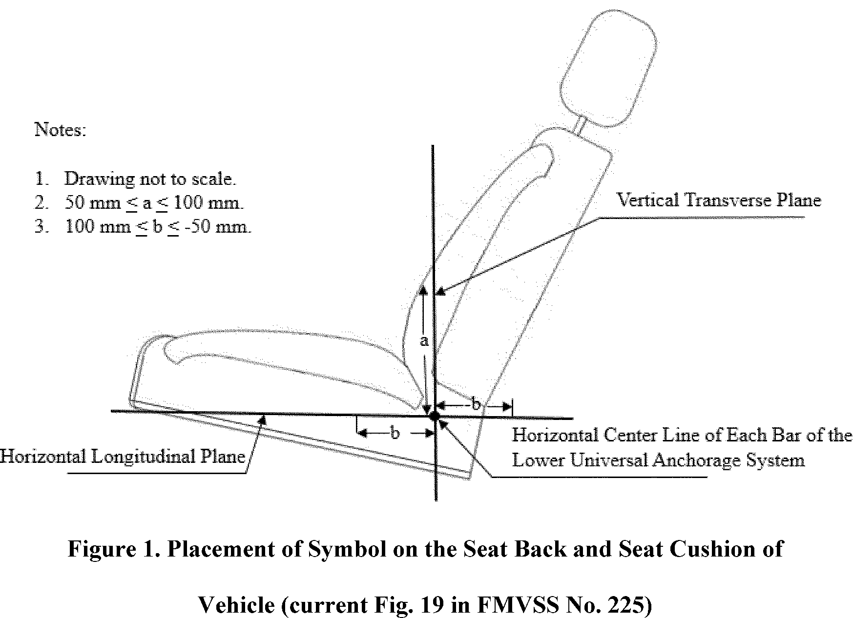
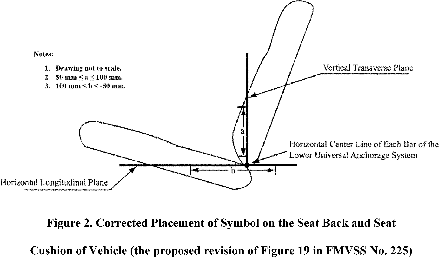
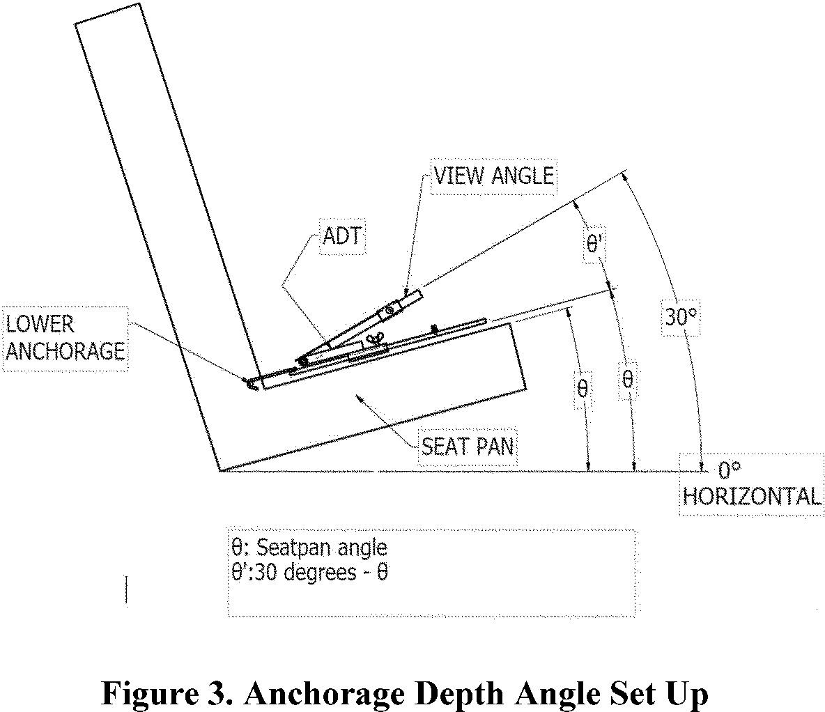
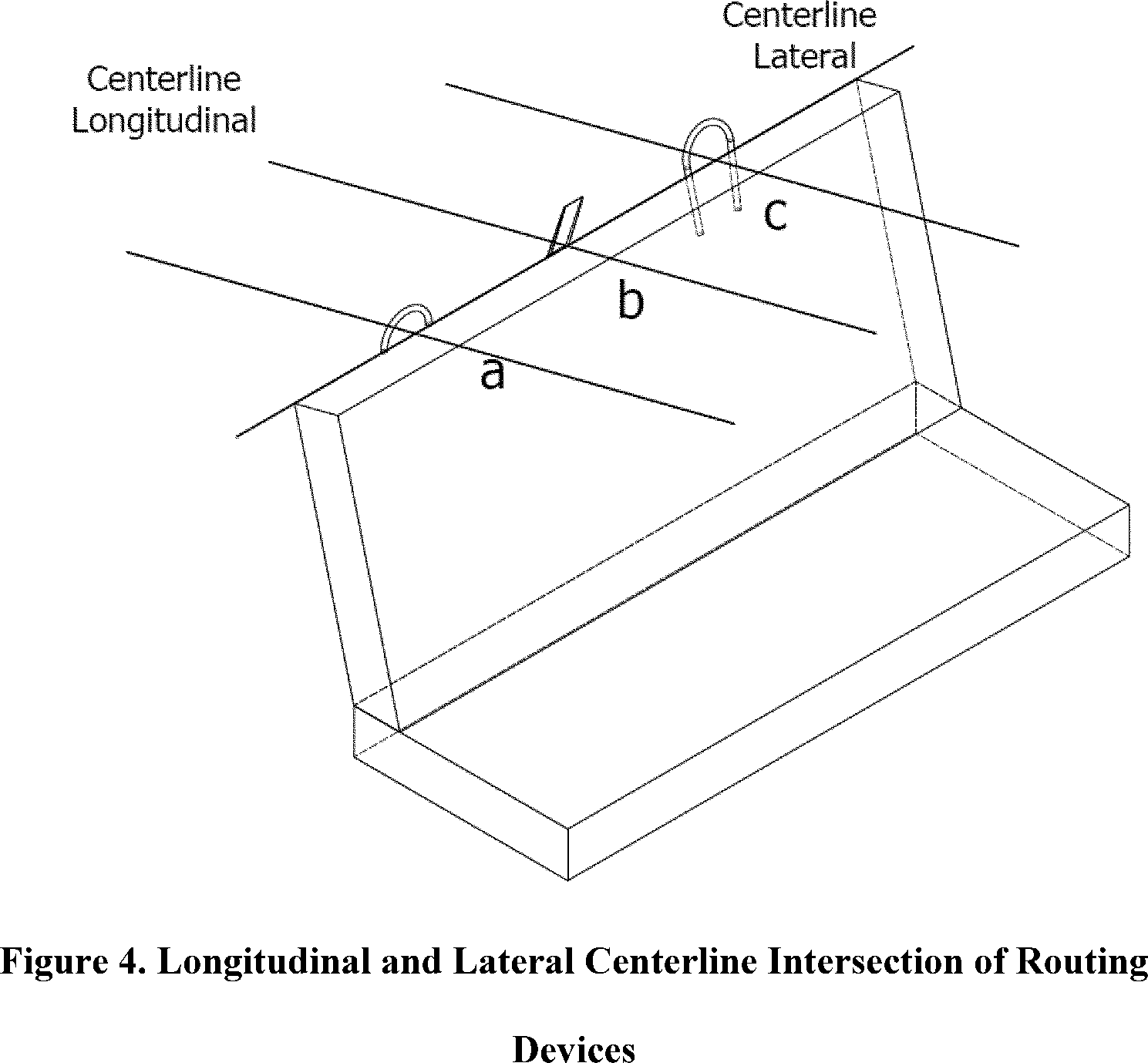
 www.dot.gov/privacy
 www.transportation.gov/privacy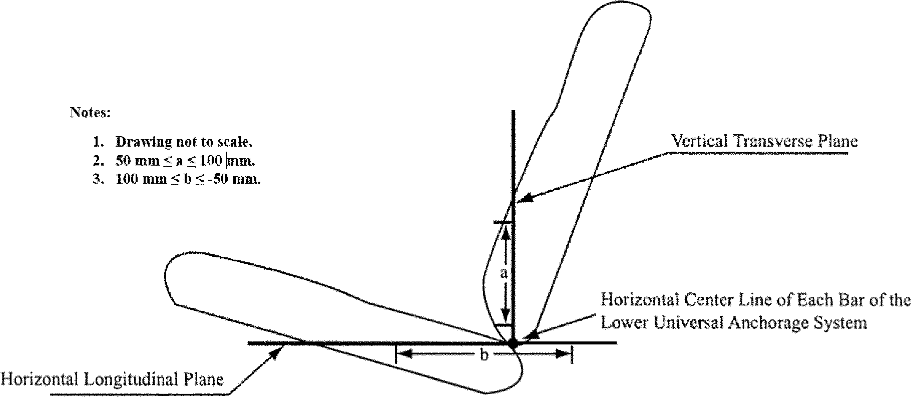
 deepblue.lib.umich.edu/bitstream/handle/2027.42/149101/UMTRI-2013-27.pdf?sequence=1&isAllowed=y
 www.tandfonline.com/doi/full/10.1080/15389588.2016.1194982
 cdn.nsc.org/cpsboard/technician_guide_final.pdf
 www.legislation.gov.au/F2012L00703/latest/text
 www.iihs.org/media/8f828313-d122-4d27-a3b0-f2b8ec60065d/tQhxoA/Ratings/Protocols/archive/LATCH_rating_guidelines_0616.pdf
 downloads.regulations.gov/NHTSA-2024-0089-0002/attachment_5.pdf